I have been working a lot with NSX-T the last few years and I have come across a misconfiguration that may cause massive packet loss for the workloads connected to Overlay segments. Since NSX-T 2.5, the recommended Edge Node design has been the “Single N-VDS – Multi-TEP” design which looks like this:
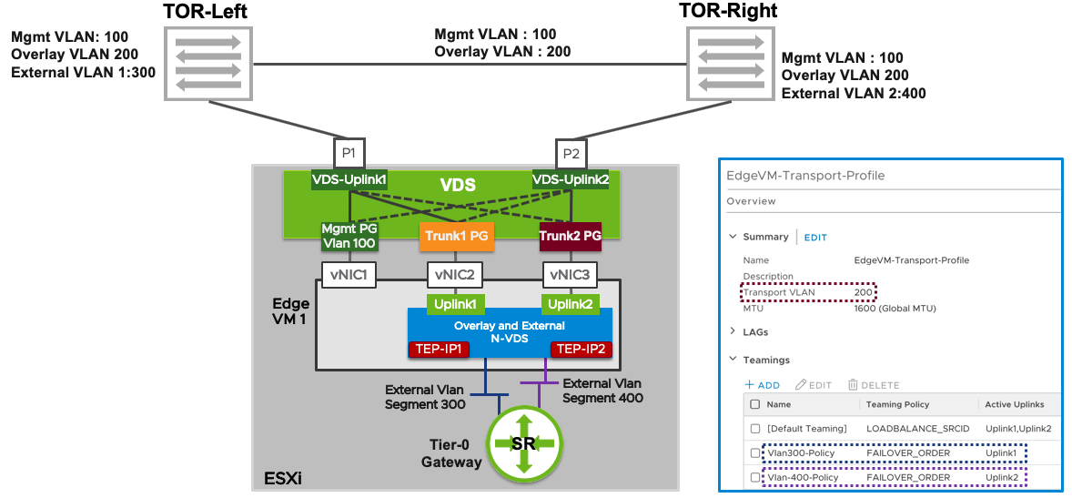
What people, and VCF, sometimes get wrong when implementing this design, is that they configure Trunk1 PG and Trunk2 PG with a Teaming and failover policy of Active/Unused instead of Active/Standby. Note that there are two TEP-IPs, each using a separate vNIC, Trunk PG and physical NIC. When one of the physical NICs or one of the Top of Rack (ToR) switches fail, the TEP-IP using that connection will go offline instead of failing over. This causes long lasting packet loss for any VM connected to a Segment that is using that TEP. I thought the Host Transport Nodes eventually would stop using the failed Edge Node TEP IP after some time, but I waited 20 minutes without any correction.
This is what the Teaming and failover Policy should look like:
Trunk1 PG
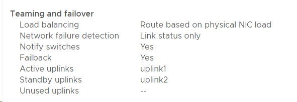
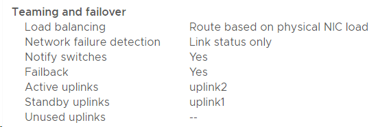
I recommend using meaningful names for the Teamings so that you can easily see on the Segments what policy will be used. Note that the opposite uplink is Standby for each Active uplink.
If you run everything on a single VDS 7.0 you may have a mix of regular Trunk PGs and NSX-T Segments on the same VDS. Same rules still apply. In NSX-T 3.1 and later you can use the same VLAN ID for both your Edge Node TEPs and your Host TEPs, but then you need to use Trunk Segments in NSX-T. So there are several options and easy to get it wrong.
One of the reasons people mess this up, is because they want to achieve deterministic peering for their uplink interfaces, meaning they want to peer with ToR Left using physical NIC 1 and peer with ToR Right using physical NIC 2, and they misunderstand how to achieve that. Named Teaming Policies in the Edge Nodes Uplink Profile will handle that and I will link to a document and a few blog posts below that will show you step-by-step how to do this, so don’t worry if you are more confused than ever 🙂
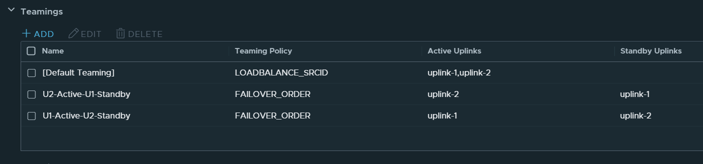
The Edge Nodes Uplink Policy should look similar to this:
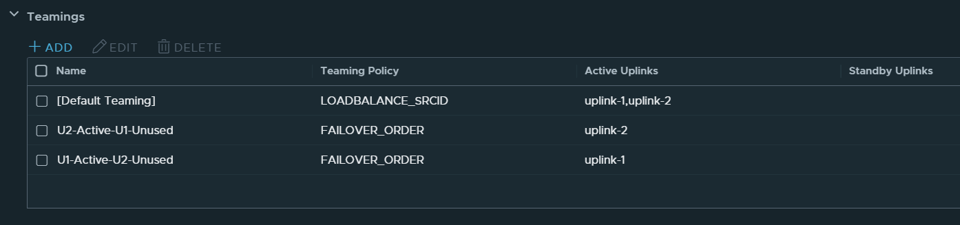
Note that there are no Standby Uplinks for the Named Teamings.
VCF 4.x and VVD 6.x also use this design, but it is documented a bit vague, so people still get it wrong. The wording has been improved in VVD 6.2 after me complaining about it, so kudos to VMware for actually reading the feedback given on docs.vmware.com and updating accordingly.
What about VCF where all of this is deployed automatically? Unfortunately, VCF 4.0 also got this wrong, but it was fixed in VCF 4.1, but only when installing it from scratch. If you upgrade an existing VCF 4.0 environment to VCF 4.1 or 4.2, the error remains. Ouch! So, if you have any VCF 4.x installations, please verify the teaming policy before it’s too late. The fix is to manually change the Teaming Policy on both Port Groups.
Simulating a physical NIC failure without involving your Networking team can be done like this:
[root@bgo-lab-esx-01:~] esxcli network nic list
Name    PCI Device    Driver  Admin Status  Link Status  Speed
------  ------------  ------  ------------  -----------  -----
vmnic0  0000:06:00.0  nenic   Up            Up           10000
vmnic1  0000:07:00.0  nenic   Up            Up           10000
vmnic2  0000:08:00.0  nenic   Up            Up           10000
vmnic3  0000:09:00.0  nenic   Up            Up           10000
[root@bgo-lab-esx-01:~] esxcli network nic down -n vmnic2
[root@bgo-lab-esx-01:~] esxcli network nic list
Name    PCI Device    Driver  Admin Status  Link Status  Speed
------  ------------  ------  ------------  -----------  -----
vmnic0  0000:06:00.0  nenic   Up            Up           10000
vmnic1  0000:07:00.0  nenic   Up            Up           10000
vmnic2  0000:08:00.0  nenic   Down          Down             0
vmnic3  0000:09:00.0  nenic   Up            Up           10000
[root@bgo-lab-esx-01:~] esxcli network nic up -n vmnic2
[root@bgo-lab-esx-01:~] esxcli network nic list
Name    PCI Device    Driver  Admin Status  Link Status  Speed
------  ------------  ------  ------------  -----------  -----
vmnic0  0000:06:00.0  nenic   Up            Up           10000
vmnic1  0000:07:00.0  nenic   Up            Up           10000
vmnic2  0000:08:00.0  nenic   Up            Up           10000
vmnic3  0000:09:00.0  nenic   Up            Up           10000
Esxtop can be used to see if the Edge Nodes vNIC fails over or not when taking down vmnic2.
Here it shows eth1 not failing over to vmnic3 when having an Active/Unused Teaming Policy:


While speaking of failover and failback testing, I would like to mention another issue that keeps coming up. When taking down one Top of Rack switch, everything fails over to the other physical NIC and we usually see one lost ping. When the switch is taken back up, everything fails back to the recovered physical NIC again, but this time we get a huge amount of packet loss. Why? Because when the switch brings the link back up, ESXi starts failing back after 100 ms, but the switch isn’t ready to forward traffic. How long this takes varies depending on vendor and switch type. We can change the network teaming failback delay to avoid this problem. Normally we change it to 30 000 or 40 000 ms.
To modify the TeamPolicyUpDelay, from the vSphere Client go to each ESXi host, Configure > Advanced System Settings > Edit. Change Net.TeamPolicyUpDelay to 30 000 and test again to see if it works better in your environment.
I hope this post was more helpful than confusing and thanks for reading.
Useful links for more information
NSX-T Reference Design Guide 3.0
NSX-T 3.0 – Edge Design Step-by-Step UI WorkFlow
Network Design for the NSX-T Edge Nodes in VMware Validated Design 6.2
Single N-VDS per Edge VM
NSX-T Single NVDS Multi-TEP Edge VM Deployment & Configuration on vSphere DVS
NSX-T Single NVDS Multi-TEP Edge VM Deployment & Configuration on Host NVDS Networking
Achieving Deterministic Peering using NSX-T Named Teaming Policies

Great article. Much appreciated.
LikeLike
Great article. I have been powering through this in my lab looking for the answer to edge uplink config and seamless failover and you have the answer.
I believe there is a new feature in later NSX version for TEP HA which should work properly.
LikeLike